Where do the new posts go?

Self-Proclaimed die Expert.  http://kam-stampingguru.blogspot.com/

Has moved. For little more than a desire to monetize my efforts with the blog I now make all my new posts there. The WordPress site was a good learning platform, but their insistence on not letting me advertise on my own content was a little too much. Even just in principle. (disclosure I have earned $0.04 to date on the blogger site) Though I am using the blogger experience as a test bed for learning. I find a little more freedom to try things over there.

Surprisingly I have noticed that this site gets a higher ranking on Google, even though the other blog is served by Google. Funny (not like ha ha, but funny as in weird)

In any case, trying something new, even though it looks to be a losing proposition. The idea that this content is worth anything and the others would pay me to keep it up.

But in either case I am trying it. See you at the new site.

My press runs at 42 strokes per minute will your simulation take that into account?

It was bound to come up sooner or later, and I even surprised myself by optimistically leaving of my list of rants and potential future blogs. But really can commercial simulation really predict the effect of press speed variation on the forming of parts?

  • yes and no (or more appropo no, but kind of)

Funny enough this has been brought up in several contexts recently. 1st by a colleague who just addressed the issue with a customer for tech support, 2nd a colleague who ran into this question during training answered it correctly only to have another more technically minded person give a roundabout not quite correct interpretation, and 3rd in a conversation with a thrid party who was relating stories of how our competition answered this question.

To break it down fact by fact:

  1. commercial simulation codes assume a single hardening curve for the entire simulation
  2. most material properties reported by steel vendors will also assume a constant and singular strain rate
  3. mild steel has a positive strain rate (which means it stretches better fast than slow)
  4. many steel parts will split if run fast in the press (and may form better in inch modes or slower press speeds)

The top two facts go to the point that most of the time when people run a stamping simulation they will not see any effect of press speed, and therefore the strain rate will not be a consideration. For example, if I run a simulation at a press speed of 1mm/sec vs 1000 mm/sec the stretching in the simulated die will show no effect (OK, if you are running a dynamic explicit solver you will see something different happen, but that would be a result of inertial effects and not a material performance issue). The rules that govern how the material is formed will refer to the hardening curve (stress/strain curve) of the material to determine how the material responds to deformation. However, since only one curve is provided there can be only one answer.

The next two facts are more interesting as they lead to people thinking I have mispoken myself and contradicted the 3rd statement with the 4th. But in fact both statements are correct. Mild steel has a POSITIVE STRAIN RATE, which means that during successive tests of the same heat of steel at different speeds of deformation, the steel will show a higher resistance to strain (deformation) when pulled faster. If the steel demonstrates this increased resistance to deformation as speed increases it means that the material will have more uniform distribution of stretching when pulled fast, and therefore would perform better fast than slow (less likely to fracture, which is a sign of non-uniform deformation).

Brief aside (that should be a footnote, but I don’t know how to do that here):

This is entirely different than the explanation given by some “dieology” gurus, or other self-proclaimed-die-experts, that steel is like silly putty. Silly putty as you might know is a material that when you stretch it slowly it stretches very far without breaking, and when strecthed fast seems to fracture quickly. BUT this is a major mistake, this is the typical thought by those who confuse formability with ductility. The slow stretching of silly putty starts a cycle of non-uniform deformation that we in stamping would consider a fracture/smile/neck. All that deformation of silly putty at slow speeds is the part failing, getting weaker and weaker because we stretched it slow. On the other hand if you attempt to stretch Silly Putty fast it fractures with almost no necking.  They offer this a an explanation as to which some parts only make when the press is run slow, but that has nothing to do with the behavior that is observed. SORRY

So does steel like being deformed SLOW more than fast? NOPE. Steel has a positive strain rate. Attempts to deform it fast result in the steel stepping up and acting stronger in the deformed area to prevent the onset of localized necking. This is GOOD, So stamping steel parts fast should be good too. In fact, if we did go so far as to load a simulation code with the appropriate steel strain rate curves, and run simulations at various speeds we would see that the faster deforming simulations would show better distribution of thinning, more uniform deformation, and therefore better forming. Again SORRY.

Another disappointing revelation. Strain rate sesitivity manifests itself only at greatly varied speeds (i.e. 10m/s to 100m/s to 1000m/s) bu the effects at relatively modest changes say 0.25m/s vs 0.35m/s won’t be noticable. Now consider, just how fast does the ram of your press go, and how much faster will it go if the cycle rate doubles. If you said double, SORRY try again. Press ram velocity for mechanical presses, will vary throughout the stroke. The ram has no velicty at the top and bottom of stroke (where it reverses direction) and will move fastest at midstroke. In most stamping operations the work of the press is done in the bottom few inches (mm) of the press stroke (usually not more than a few degrees of crank angle (maybe 15-20) and therefore will not be near the area in the stroke when a doubling of press cycle time = double ram velocity.

doing the math for a press with a 1 meter stroke at 10 spm to 20 spm. I’ll even spot you average press speed. at a rate of 10spm the ram covers 2m each 6 seconds (or 0.33 m/s). When we double the cycle rate to 20spm thats 2m each 3 seconds (0.66m/s).  You would be hard pressed (no pun intended) to find data on the variation in strain rate sensitity for such a low strain rate variation.

So why do my dies produce splits more readily at these high cycle times?

In the above question you find the answer. It may be the dies, not the steel.

Your dies don’t behave well at higher speeds than they do at slower speeds. Sorry to say that everybodies favorite scapegoat: the material. might not have anything to do with this problem. More likely your press and die are not behaving in a consistent manner from fast to slow:

  • press alignment is more likely when we cycle slowly, at high rates the press can remain crooked and unevenly distribute forming pressure
  • Die alignment is better slow than fast
  • Your lube might work better at slow sliding velocity than fast
  • The die doesn’t dissipate heat as well when cycle time is fast
  • you pressure system (nitro springs, etc) might show speed sensitivity
  • Your part location system might be unstable at high speeds
  • Your automation might locating the part different at higher rates (especially pneumatic systems which can’t drop as fast as we like just cause the press is running faster)
  • trapped air under the part or in die can affect forming more in fast speed than slow (venting issues)

just to name a few that come to me at the top of my head.

Can simulation give me any indication?

indication yes. but not a direct answer.

If we run a system of simulation runs (stoichastically) allowing for slight variations in binder pressure, friction, Lube, bead effect, blank location, material variation, and thickness variation. We can discover if a process is prone to variation in results for these changes. If a process is fully insensitive to variations due to the changes then we know that the process should produce favorable results at nearly any speed. But if the process shows that results are highly variable (goes for safe to splitting) for minor changes in bead effect, or blank location, or lube (friction) then we can recognize that the process will not be robust, and could be vulnerable to variation if something like press speed were varied.

What is Compensation?

Springback compensation is one of the hottest topics out there in the stamping field. Whether we are looking at Simulation solutions, Scanning and reverse engineering solutions, or plain old fashioned dieology. In all these cases compensation is a geomtry adjustment applied to the tool to accomodate the elastic deformation that prevents attainment of the desired shape of the product. i.e. If springback causes a flange on a part to spring outboard of desired shape by 6 degrees–one compensation strategy might me to over bend the part 6 additional degrees beyond the intended shape so that when the part springs back it lands in the right spot.

This strategy of geometric compensation is the most common approach to addressing the springback problem in todays stamping industry. It has historically proven to provide reasonable results and there is much anecdotal and scientific evidence to support it. However, there are many issues with geometric compensation:

  1. the altered tooling geometry needed to achieve might not be feasible (the overbend in the example is now not possible with given geometry)
  2. the fix costs alot of money (new CAMs added to the die to achieve the over bend are more expensive and complex than production allows)
  3. The mode of springback will not be beneficially adjusted through geometric compensation
  4. the compensation is, in fact,  a new deformation mode that it self induces a different springback (now that we have adjusted the process it springback more, or less, or just different)
  5. The springback is not a repeatable outcome so sometimes it is too much compensation (the part now is 1-2 degrees closed) other times it is 1 degree open.

It seems though that whenever discussing springback compensation with potential customers, too often they assume that when we say it is not possible to compensate for some mode of springback that it is that our technology can’t and that somebody elses can. It is perhaps our own fault for honestly portraying the capability of springback compensation (geometry based) as an imperfect solution. Because there are some springback behaviours that just can not be compensated for EVER. I know it is unpopular to say, and even more insulting to point out that there are just some things that the magic of geometry manipulation just cannot get done.

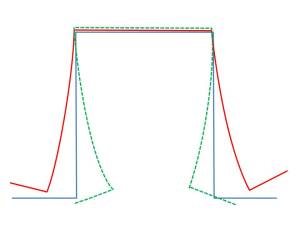
For this rant let us focus on issue # 1 from the above list. (altered tooling geometry results in an infeasible tooling condition). For all those who have been recently initiated into the world of stamping Advanced High Strength Steel (AHSS) for structural members–you will appreciate this. On significant springback effect with such parts is side wall curl. If the wall of a “hat” section of the rail is formed by sliding over a radius (i.e. draw/die radius from a binder) then the springback behavior is often times a curling effect (not unlike curling ribbon over the edge of the scissors when we wrap christmas presents). If the design calls for a stright 90 degree wall, this curling will cause a significant assembly issue and must be resolved. If we feed this mode of springback into a “compensation module” of nearly any software that offers the function, we will recieve a recommendation to counteract the springback effect by curling the wall in the opposite shape.

Geometry Compensation of sidewall curl (blue design, red wpringback, green compensation)

Geometry Compensation of sidewall curl (blue design, red wpringback, green compensation)

Such compensation geomety would create an impossible (nearly) forming condition in the die. Yet this would be the approach that a geometric compensation tool would recommend (whether a simulation code derived, reverse engineering/scanned method, or good old fashioned guesswork). As you can hopefully see this is not an option.

  • The direct forming action of the press can’t work under the backdraft area
  • To address without using CAMs would mean two separate tipping stages, forming the legs of the flange in two separate operations
  • To use CAMs we would need double collapsing cams for each side and a tremendously strong tool to induce the deformation required to overcome the AHSS strength
  • If that part ever sprang back less than predicted then the part would stick to the bottom tool
  • The deformation behavior will change with the compensation greatly, and the part will show a different behavior

The conclusion here is that compensation is not possible. But it may be possible to provide a countermeasure to the springback, which may require design changes to the product, adjusted assembly processes, or even an entirely different concept for the part. But sadly NO SILVER BULLET. No perfect answer for springback compensation. No instant answers.

Sorry.

Simulation Accuracy (What? Again?)

It seems that maybe i can’t write enough on the topic of simulation accuracy; and maybe that is true. Or maybe I am dusting off the cobwebs around my critical thinking portion of my brain. So, I do need to revisit the topic. Just in case I have not thoroughly offended any body’s sensibilities.

To date I have:

So here is a little bit of damage control.

  1. accuracy matters, But to pursue the accurate solution when the inputs are assumptions and NOT KNOWNS, how good is that accuracy
  2. Be as accurate as you need to be at the time of simulation-during preliminary feasibility when so many variables are not defined allow for some “fudge” if it helps you get an answer in time to make a difference
  3. Don’t split hairs over tenths of a percent strain when we are looking for failures which are predicted on a scale that was devised using a rusty pair of point micrometers
  4. Don’t assume that a safe simulation is all that you need, passing simulations at all costs usually result in poor assumptions that are not acceptable in reality
  5. Keep your failing simulations (and the inputs that created them) they are easily as important as those that pass later since you may need to explain why you move the design in a particular direction

You see, I am not a crank who is anti simulation. ON the contrary I love simulations and do heartily believe that we cannot get by without it. But I also try to take a pragmatic approach to its application and am constantly asking me, if I am getting the feedback that i need in time to make a difference. Because I don’t care how accurate a simulation claims to be if the feedback takes so long to get that I miss oppurtunities to apply the knowledge gained and benefit from it, then I don’t need it.

I can see that I have a lot of baggage in this area so maybe I need to structure my arguments better.

All things held equal, this simulation is VERY ACCURATE!

Simulations, although we may run many iterations, and many alternatives in the pursuit of the passing result are but one result. How can we claim results are ACCURATE when the EXACT conditions that we simulate might never exist in the real world.

Yes the crash analysis results for a 35 mile an hour offset impact were good, BUT. How often will the crash happen when the car is super accurately being pulled toward a perfectly square target, that perfectly bisects the front bumper of the car, with one adult exactly 185 pounds, 5’10”, blah blah blah.

Or how likely is it that when the steel arrives at the stamping plant it will be EXACTLY 0.65mm thick, with a homogenous coating of 0.12 friction lube, and a YS of EXACTLY 390MPa, TS of 690MPa, n value of 0.16, and R bar of 1.1??????

Robustness matters as much as accuracy

Yes accuracy matters. And most commercial codes deliver very reasonable accuracy.

But the question not enough people ask is whether or not the situation simulated is very likely to happen again, and how will the tool/process respond in those circumstances? It is as if. Stamping experts who in the “real world” will insist on conducting a 50-100 part study for statistical repeatability before buying off on a die, just turn off that part of their brains when they buy of on a single passing simulation result. “Oh, the 100th iteration finally passed??? Good lets use that one as our engineering basis and build the die!”

We need to–as an industry–consider the variability in our system and stop the madness of buying off on that single passing result. No did shop would accept as proof of the die we build a single part delivered on a feather pillow as proof that the die worked. We always would place the die in the press, run it at rate. and randomly collect the parts put them in rack ans then measure them.

In fact, I used to really upset people by waiting until they had unset the die to ask for one or two more panels, to see if the set-up could again replicate the success we just had in the first run-off. You could almost guess the rate of success ahead of time by how angry the die makers got, when asked to re-set the die (I suppose because they just went through a bloddy awful time getting the first run off to even run).

Let’s not even talk about springback until we can demonstrate that the splitting and wrinkling saftey we have achieved is repeatable. Because if it is not you can bet your last sheet of visqueen that the die conditions will change and all the springback analysis we ran will go straight out the window as the beads, lube, blank, and binder undergo tremendous adjustments.

Accuracy, Smaccuracy

I love the word ACCURACY. In the FEA field we use it all the time.

  • FEA user: “How accurate is you code?”
  • FEA guru: “Very accurate. 99% or the time the answers are perfect”
  • FEA user: “wow. What differentiates the 1% lost accuracy? In what situations does it happen?”
  • FEA guru: “Nobody knows. But we’re working on it.”

Now that never gave me warm fuzzies. In fact it really made me wonder about alot. Because if we don’t know what makes that 1% happen, then it might as well be less than 50% accurate, or 10%, or 0%.

Even better is when FEA gurus tell me that they got really accurate results when they reworked the mesh, played around with contact algorithms, shuffled in alternative material models, or altered time steps. Often they mention that they did so because they say the the initial results did not match some master set of data. OK yes you achieved a REALLY accurate result. But was it predictive? If you did not have the litmus test of the pre-existing results, could you have trusted the initial results? Because if the answer is yes, or maybe, or no. Then the illusion of accuracy is all you had.

Some CAE analysts will hold up the fact that because one code has the most “lever” and “buttons” that allow one to adjust the resulting calculations that those codes are the most accurate. But that tends to make them less predictive. If the model is not predictive then what good came of it?

  • Truth: simulation of sheet metal stamping is just as accurate these days at most of the tools we would use to measure it.
  • Truth: If a simulation result is too dependent on the operator to generate an “accurate result” then the tool itself is potentially unreliable.
  • Truth: the reliability of the results will often depend on how well the real world is represented in the simulation input
  • Truth: the real world is less reliable than the simulation, because the real world does not stand still it changes

It is not a beneficial feature of a FEA code if I can alter the outcome via application of my extensive knowhow of FEA theory. Becuase if we rely on that to generate the result, can I believe that the result was not a fabrication?

Variability will be discussed separately.

Comprehensive evaluation of design

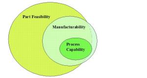
Computer Aided Engineering and Finite Element Analysis maturation as accepted technology has brought with it some undesirable baggage–the conclusion that just because something is feasible that we should proceed. It is a fact that a passing result from an analysis does, in fact, prove that a design is feasible; and therefore perhaps worthy of fulfillment. And that validation of a given design is in fact more cost effective and more likely to produce an on time result than some other design that was NOT validated. BUT in todays world we can assume that all designs may undergo some method of CAE or FEA validation. So that being feasible is not the end of discussion.

Let’s assume that all ideas can eventually be proven using FEA/CAE or adjusted to make them feasible. Then we need other criteria to evaluate which designs are best to pursue. There is much more to bringing product and processes to market than just showing that it is possible. We now must move forward and try to evaluate if we SHOULD proceed, not just CAN we proceed.

Below find my first feeble attempt at a mondaydots ™ like video to illustrate what I mean.

Stamping Engineering and FEA role in it

A faulty paradigm I am currently dealing with-in attempts to bring Sheet Metal Stamping Technology Solutions to the market-is the perception that FEA tools (my companies primary product line) are merely go or no-go decision tools, and that the users should use them to Pass/Fail the designs in front of them. But how true is that?

mondaydots hybrid: fastworks from jeff monday on Vimeo.

After viewing the embedded mondaydots video discussion, I even more thoroughly believe that most of the engineers and designers that work in the sheet metal stamping world are not making simple go/no-go decisions. After all sheet metal stamping is not a NET-SHAPE-PROCESS. Instead it is a near-net-shape-process. The designer has to decide the path used to arrive at the net shape and the path selected has profound effect on the Quality-Cost-Time_to_delivery of that manufacturing process.

Many view the FEA tool as a tool that is used to merely prove that the design is feasible or not. But the process as simulated is a result of some assumptions and options selection made by the designer while setting up and boundary conditions of the simulation. After the results are computed the analyst will often have to choose different boundary conditions to achieve the passing (desirable) result. But we find that they often do not manipulate the full set of assumptions but only a subset of those variables. Which means that when they arrive at the feasible result, they may have gotten there along a “path” that took them further away from some higher order objective. Why? Because the tools afforded them (FEA) do not allow them to qualify the other assumptions. (I assume that my approach is the cheapest, so I tweak only the variables that keep me along that branch of assumptions. Failing to see that after a while the cheapness assumption may be over ridden by some new variable I introduced to achieve my “best result along this path”.

This brings me full circle to my earlier puzzling over the Venn diagram of feasibility-capability.

just because it can be made, should we?

just because it can be made, should we?


We all make microdecisions that require some justification (evidence) regarding the validity to our current understanding of the circumstances. And if we pretend that our decisions are only go/no-go when in fact we are supposed to be looking at and weighing alternatives we are setting ourselves up for eventual failure.

Change–still difficult to sell amid these hard times

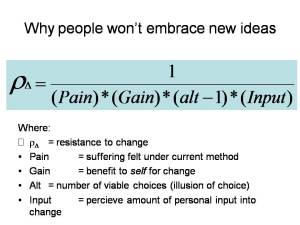
Why do people resist change?

Why do people resist change?

If any of the variables (pain, gain, input, or alternatives) go to zero then resistance in infinite.

In preparation to an upcoming product management workshop I am preparing for my sales colleagues I tried to define (again) how we are supposed to get our customers and prospects to accept new ideas on how our (or any other software) fits into their process. It seems that when you want to promote your product and the product is in some ways a departure from the norm that this is a near exhaustive exercise.

In the early days of FEA we sold through much effort the game changing idea, that you need to use FEA (finite element analysis) to solve on the computer problems that are much more difficult to resolve in the “real world”. This took time, and the sales people of the day had to do alot of evangelizing about the need for math based evaluation.

Now that math based engineering is considered common place, when new methods or new implementations come along, we end up having to fight these battles again. Unfortunately, the passionate advocates for doing things better or smarter are now fighting their own internal resources “why would I work to sell this new idea, how does that put money in the bank?” We must convert the faithful. This it turns out is even harder than converting the non-believers.

Is it just me? Or is there a certain amount of “Innovation Inertia” that has overtaken the world?